Instrument P Id Drawing Symbols
Piping Instrumentation Diagram Instrumentation Forum
How To Read Piping And Instrumentation Diagram
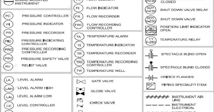
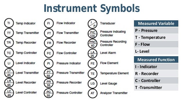
Instrument Abbreviations Used In Instrumentation Diagrams P Id Learning Instrumentation And Control Engineering

P Id Symbols With Letters Piping And Instrumentation Diagram Diagram Abbreviations

Interpreting Piping And Instrumentation Diagrams Symbology Aiche Piping And Instrumentation Diagram Process Control Electronic Data Systems

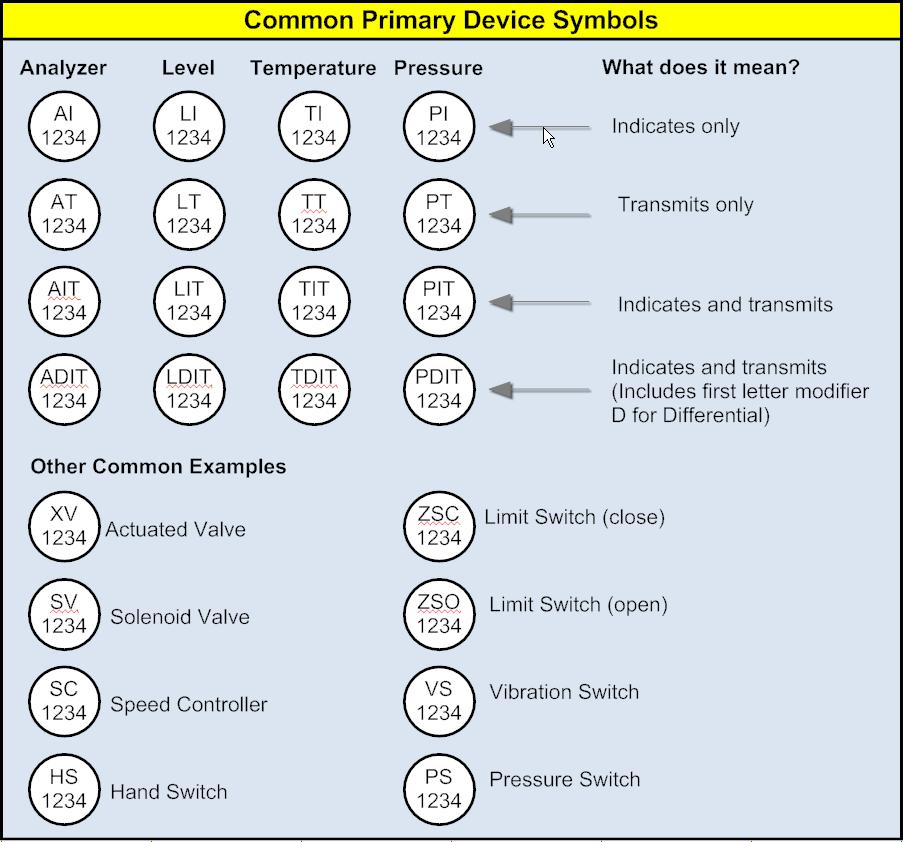
P Id Common Symbols How To Read A P Id Instrumentation And Control Engineering
In the process industry instrumentation symbols are based upon isa standard s5 1.
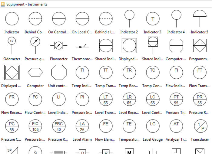
Instrument p id drawing symbols. These instrumentation symbols can easily change in types by clicking the quick action button while designing. Here i have tried to cover symbols that regularly used on the p id and pfd. We ve broken them down into seven main groups. Numbers on the p id symbols in instrumentation diagrams represent instrument tag numbers.
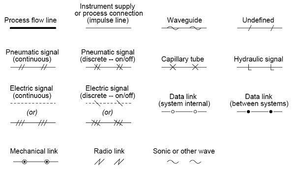
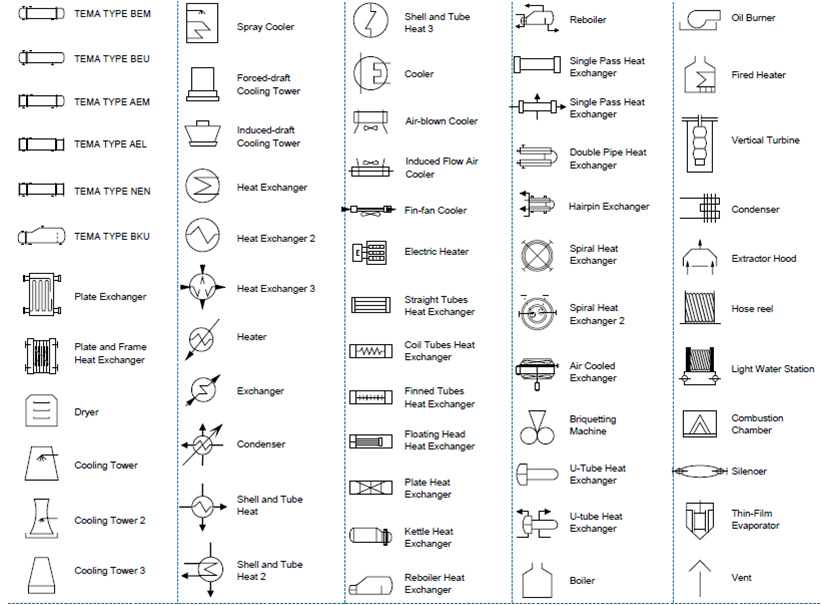
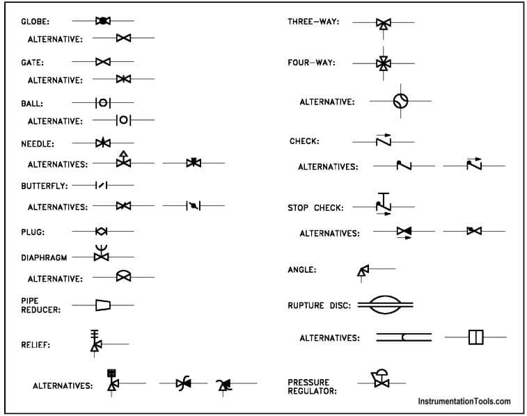
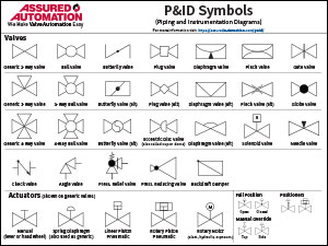
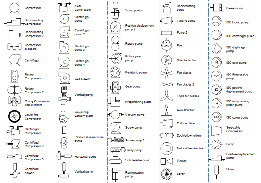
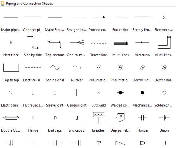
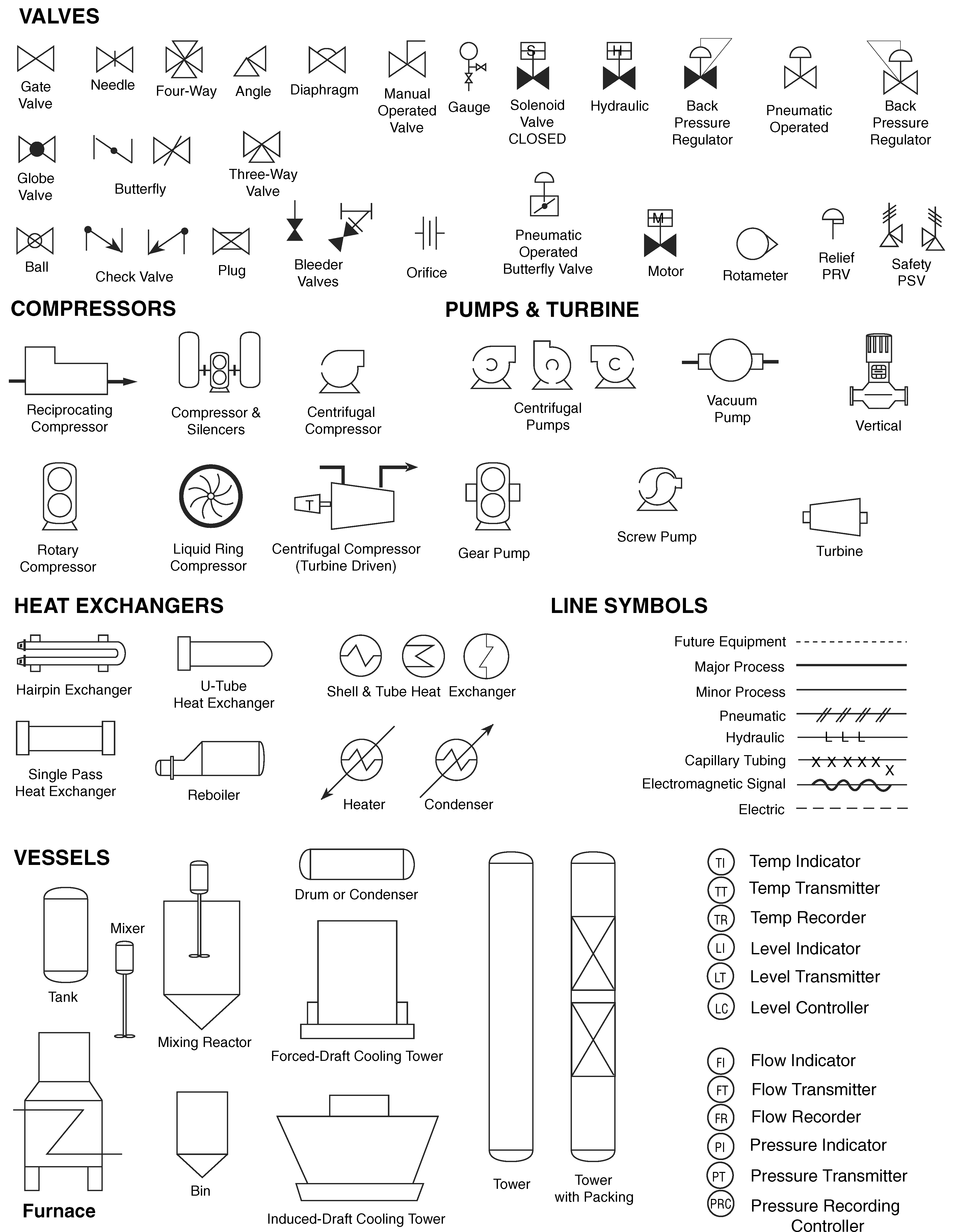
Pfd is a process flow diagram. I have dealt with some of these symbols before but here i have given a comprehensive list of the common p id symbols of process equipment such as valves flowmeters piping line connections and much more. In the process industry a standard set of symbols is used to prepare drawings of processes. Because of this a large amount of the symbology appearing on p ids depicts instrumentation and instrument loops.
Pfs means process flow scheme and pefs means process engineering flow scheme. With large pre drawn examples and more than 8500 symbols drawing couldn t be easier. A piping and instrumentation diagram p id is defined as follows. For piping instrumentation the symbols are in compliance with iso standard 14617 6 and are used for the identification of measurements within the process.
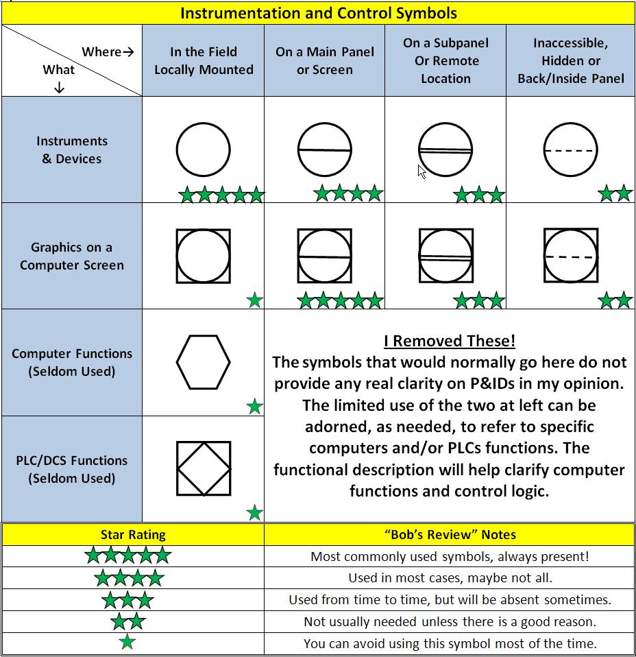
One of the main purposes of a p id is to provide functional information about how instrumentation in a system or piece of equipment interfaces with the system or piece of equipment. A diagram which shows the interconnection of process equipment and the instrumentation used to control the process. One easy way to learn how to read p id drawings and become proficient in it is to look at a lot of piping and. The p id standard issued by pip is enclosed in pip pic001 piping and instrumentation diagram documentation criteria which defines the p id format drawing size item layout tag format text arrangement etc symbols drafting rules and tagging and numbering scheme for the equipment tanks exchangers pumps reactors etc piping piping lines valves and fittings and.
The symbols used in piping and instrumentation diagrams or drawings are many and varied. The symbology for the identification of the measurement and control instrumentation on the flow and process diagrams and on the p id piping instrument diagram commonly called p i piping instrumentation is generally compliant with the standard isa instrumentation society of automation identified as s 5 that is composed of identification codes and graphic symbols. P id is a process or piping instrument diagram. The shapes in this legend are representative of the functional relationship between piping instrumentation and system equipment units.
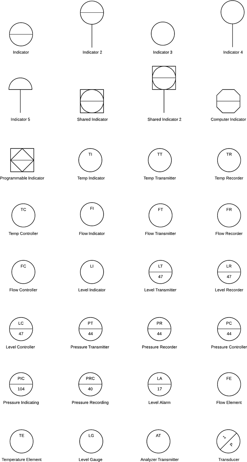
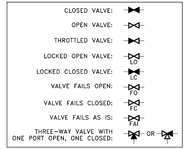
P id symbols are a standard set of symbols used to represent components in a system. P id instruments symbols process flow diagram use symbols and circles to represent each instrument and how they are inter connected in the process. Often these numbers are associated with a particular control loop e g temperature indicator and controller 123 as shown in the diagram below. With lucidchart it s easy to access all of the featured p id symbols.
Interpreting Piping And Instrumentation Diagrams Symbology Aiche
Piping And Instrumentation Symbols Instrumentation Tools
Interpreting Piping And Instrumentation Diagrams Symbology Aiche
What Is A P Id Beginner S Guide

Instrument Symbols Bmp 429 427 Piping And Instrumentation Diagram Flow Chart Process Control
P Ids Piping Instrumentation Diagrams And P Id Valve Symbol Library Assured Automation
Piping Instrumentation Diagram Instrumentation Forum
P Id Document Reading Example Instrumentation Tools
How To Read Piping And Instrumentation Diagram

P Id Common Symbols How To Read A P Id Instrumentation And Control Engineering
P Id And Pfd Drawing Symbols And Legend List
Piping And Instrumentation Diagrams

Piping And Instrumentation Diagrams Tutorials Iv Learning Instrumentation And Control Engineering