P Id And Isometric Drawings
P Id Vs Isometric Drawing Chemical Engineering World
Piping And Instrumentation Documents Instrumentation Tools
Valves Symbols Used In P Id And Piping Isometric Drawings With Detail Explanation Youtube

Isometric Drawing P Id Pipingweldingnondestructiveexamination Ndt Youtube

Isometric Draw For All Installation Autodesk Community

Pipe Spool Drawings Punchlist Zero What You Need To Know

P id and pfd symbols.
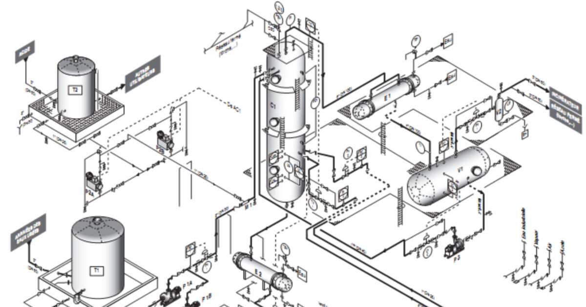
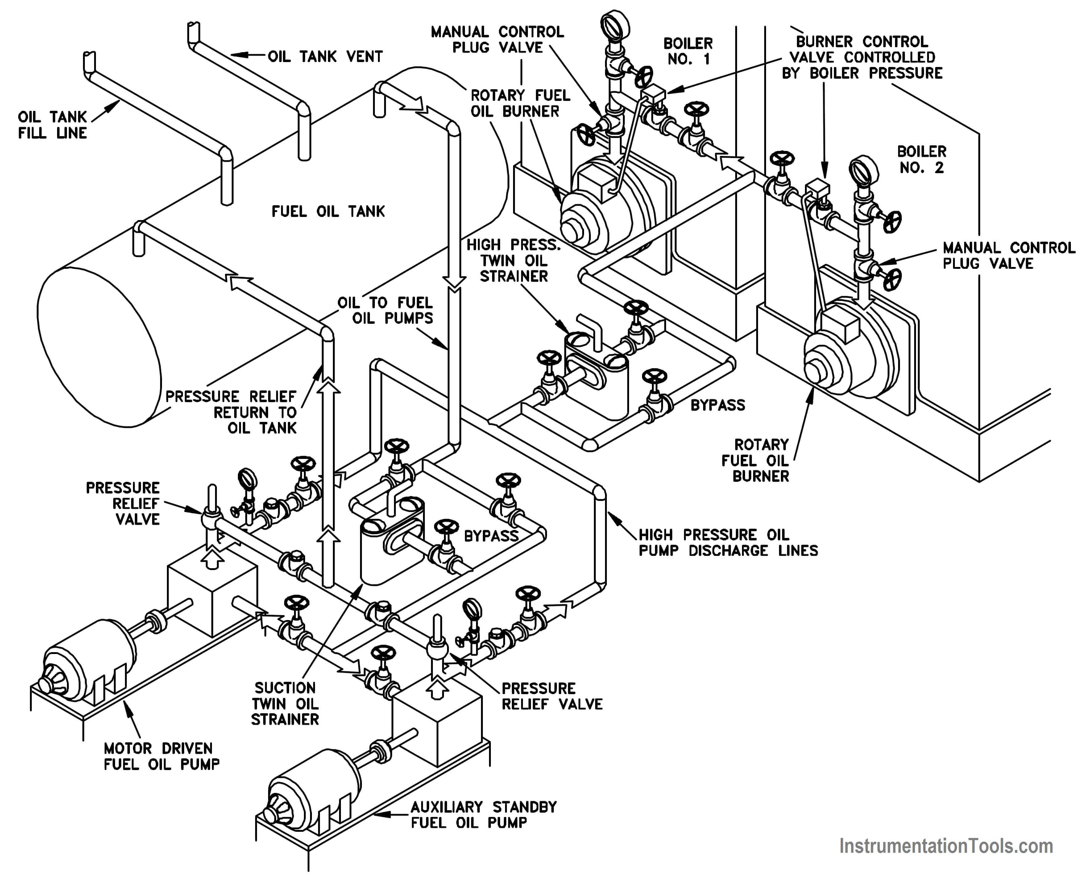
P id and isometric drawings. Let s confirm this with the help of actual p id. Isometric drawing is a method for visually representing three dimensional objects in two dimensions in technical and engineering drawing. Support and structural details are also not included in p id. How to read the process flow diagram pfd this is a pfd of the flushing oil system that shows the entire system of pump seal flushing oil.
There needs to be a link between inventor and acad p id so that i can create piping in inventor and then zip over to p id and boom generate an iso and a p id from my inventor pipe routes. P id is a flow diagram which indicates general flow of of plant process and equipments. A piping and instrumentation diagram pid is a detailed representation of the all the process. These drawings detail each pipe spool ready for manufacture and assembly.
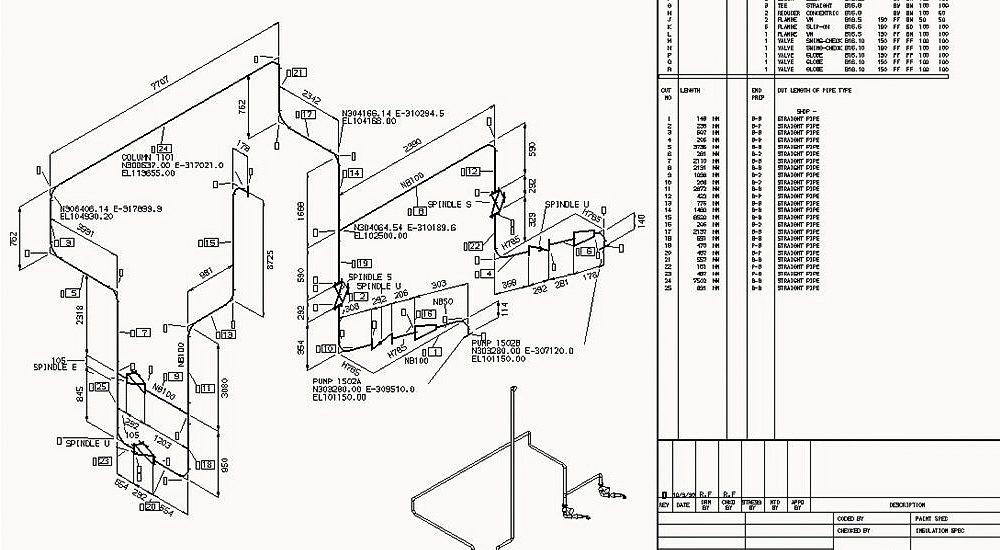
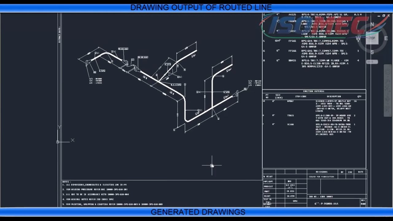
Isometric drawing is a two dimensional 2d drawing that represents the 3d piping system. Process parameters p id no pwht testing requirements insulation painting specs etc match with the line list if given in the isometric. Iv piping isometric means isometric view of pipe line between two points in consideration drawn to the scale gives correct detail of bill of matrial needed for execution of the piping job. The correct isometric revision number is mentioned in the title block.
As a start you may take any p id and compare it to the respective isometric drawings. When the above tasks are undertaken using traditional drafting methods or even with specialised but separate unintegrated software packages this results in poor re use of information between the design stages. August 19 2020 at 3 54 pm. Pumps and turbine p id symbols.
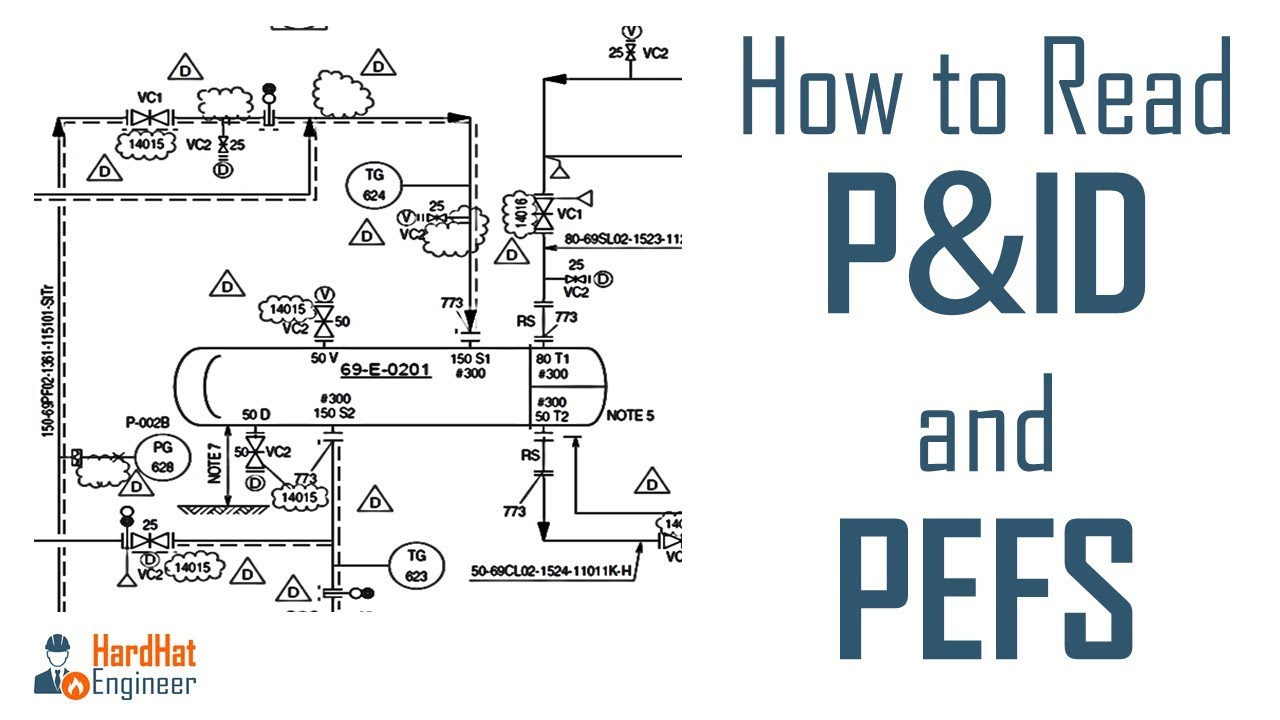
P id vs isometric drawing. The technique is intended to combine the illusion of depth as in a perspective rendering with the undistorted presentation of the object s principal dimensions. There are few iso and british standards available that provide symbols and best practices to draw pfd and p id such as isa s5 1 bs 5070 and iso 10628. Pipe class printed at the bottom of the drawing matches with that in the line number.
Start from one point till the end. P id symbols are a graphical representation of physical equipment that installed on the field. Ok now you know what p id is and types of information you re going to get from the drawing. Means process instrumentation diagram it is showing piping with instrumentation control system generally not drawn to scale.
Lastly piping isometric drawings are generated for the pipework. P id vs isometric drawing pid and piping isometric drawings both diagrams are used in process and chemical industries for the sake of representation of the processes of the plant and for training the operators and engineers about the plant and the processes.
Automatic Piping Isometrics From 3d Piping Designs Piping Isometrics M4 Plant

Piping Isometric Drawing Checklists Isometric Checklist What Is Piping All About Piping Engineering

P Id Diagrams And Pdms Modeling From Point Cloud Data

P Ids 3d Pipework And Piping Isometrics In One Integrated System
P Id Isometric Views Of A Plant

003 Basic Piping Isometric Drawings

Pin On Drawings
Piping And Instrumentation Documents Instrumentation Tools

Valves Symbols Used In P Id And Piping Isometric Drawings With Detail Explanation Youtube

Piping Isometric An Overview Sciencedirect Topics
Draw Piping Isometric Drawings By Isomac Software Youtube
Piping Coordination System Piping Isometrics Isometric Views And Orthographic Views

How To Check Line Isometric Drawing To Piping Instrument Diagram Or P Id Pipefitter Youtube
