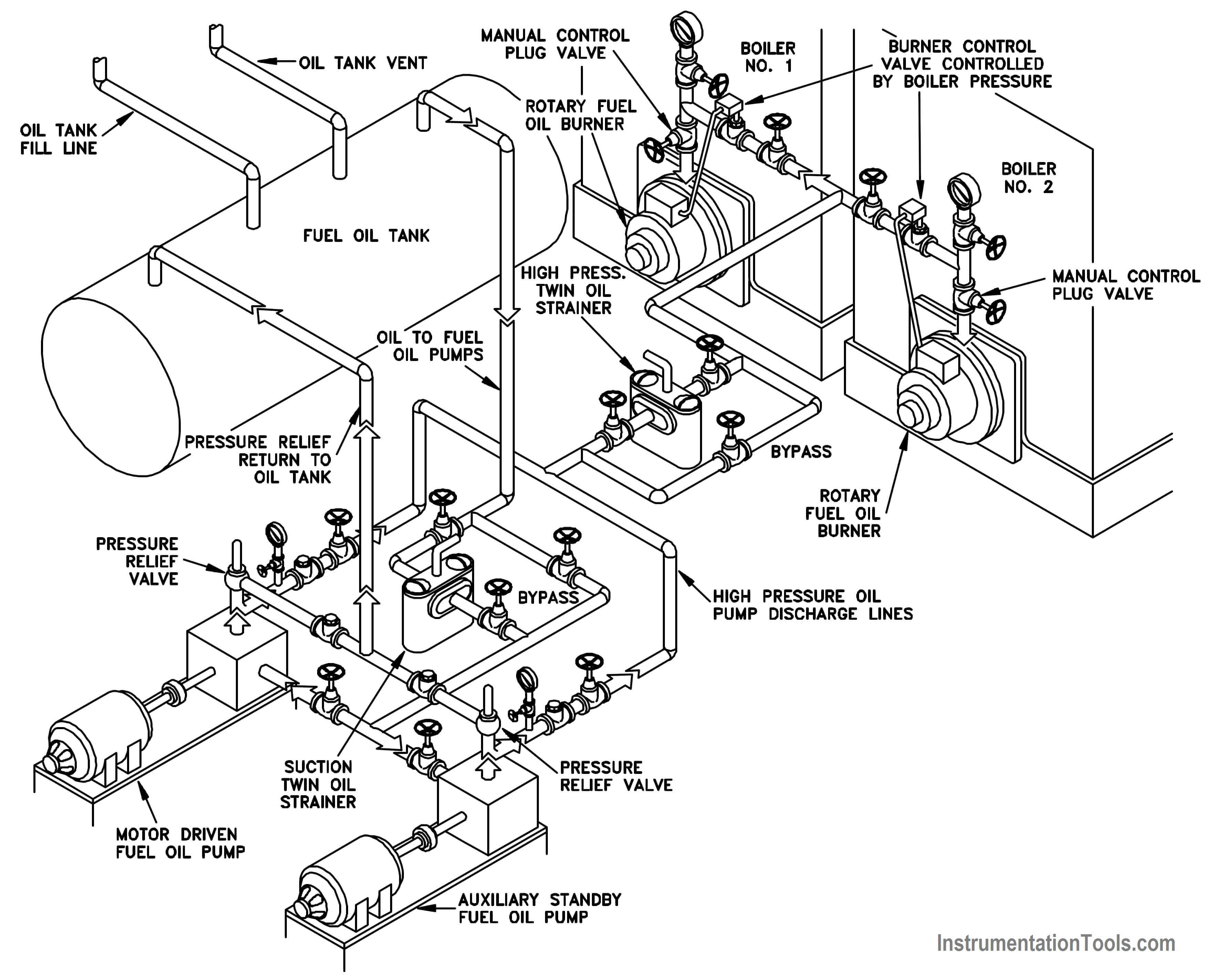
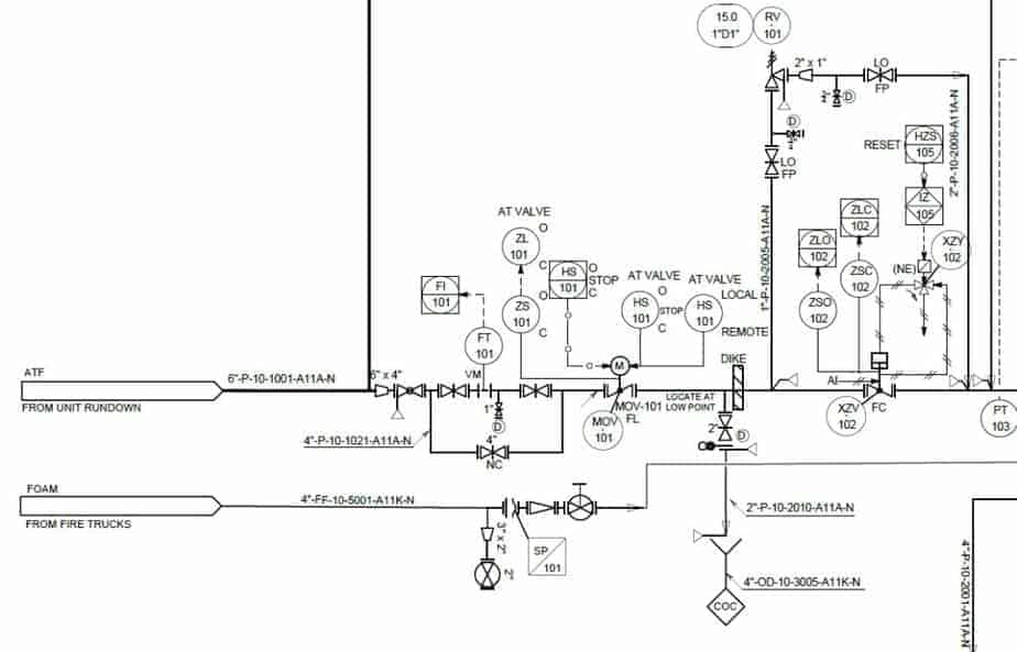
P Id Drawings Explained Pdf
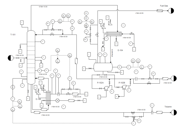
To help locate a specific point on a referenced print most drawings especially piping and instrument drawings p id and electrical schematic drawings have a grid system.
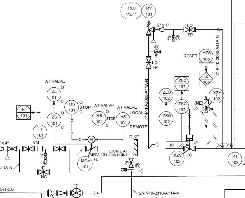
P id drawings explained pdf. Process instrumentation diagram graphical description of the process and process equipmentgraphical description of the process and process equipment using standard symbols ansi isa s5 1 instrumentation symbols and identification the p id is used by field technicians engineers and operators to better understand the process and how the. 3 aarx 304l s s 1 f 3 aarx 304l s s. The single line format is most commonly used in p ids. This practice applies to all diagrams that fit the definition of a p id in section 3.
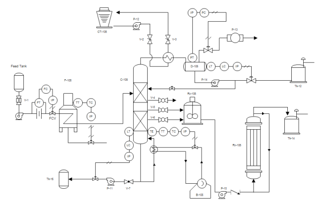
These controllers communicate over a communications bus and pass variables back and forth between the iop input output processor sections of the dcs. Figure 12 is an example of a single line p id. Reviews the information contained in the non drawing areas of a drawing. The requirements provided in this practice can be applied to any cad system used for developing the p ids and are not vendor hardware or software specific.
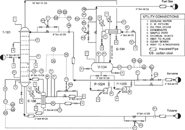
A set of standardized p id symbols is used by process engineers to draft such diagrams. And provides several examples of how to read a p id. Single line p id drawings. All system equipment is represented by simple standard symbols covered in later modules.
Reviews the common symbols and conventions used on p ids. A piping and instrumentation diagram p id is a graphic representation of a process system that includes the piping vessels control valves instrumentation and other process components and equipment in the system. Downloadable pdf of valve actuator and other popular p id symbols. Module 3 electrical diagrams and schematics.
Loop diagram symbols and p ids this p id diagram illustrates the use of software data links between controllers. P id is the acronym for piping and instrumentation diagram i e. Module 2 engineering fluid diagrams and prints this module introduces engineering fluid diagrams and prints p ids. The grid can consist of letters numbers or both that run horizontally and vertically around the drawing as illustrated on figure 2.
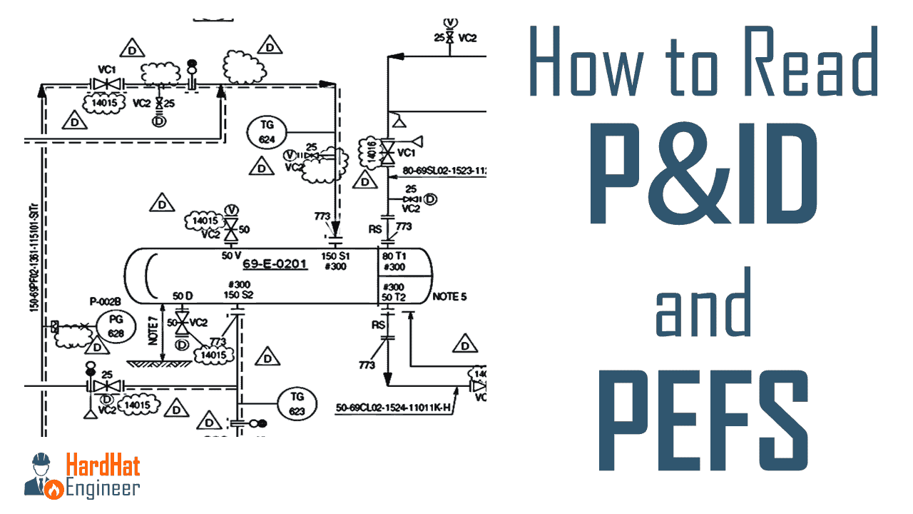
Learn how to read p id from the expert. Subscribe https goo gl 9oktfa you will learn how to read p id and pefs with the help of the actual plant drawing. The communications processor will then put the information in.
