P Id Drawings Pdf

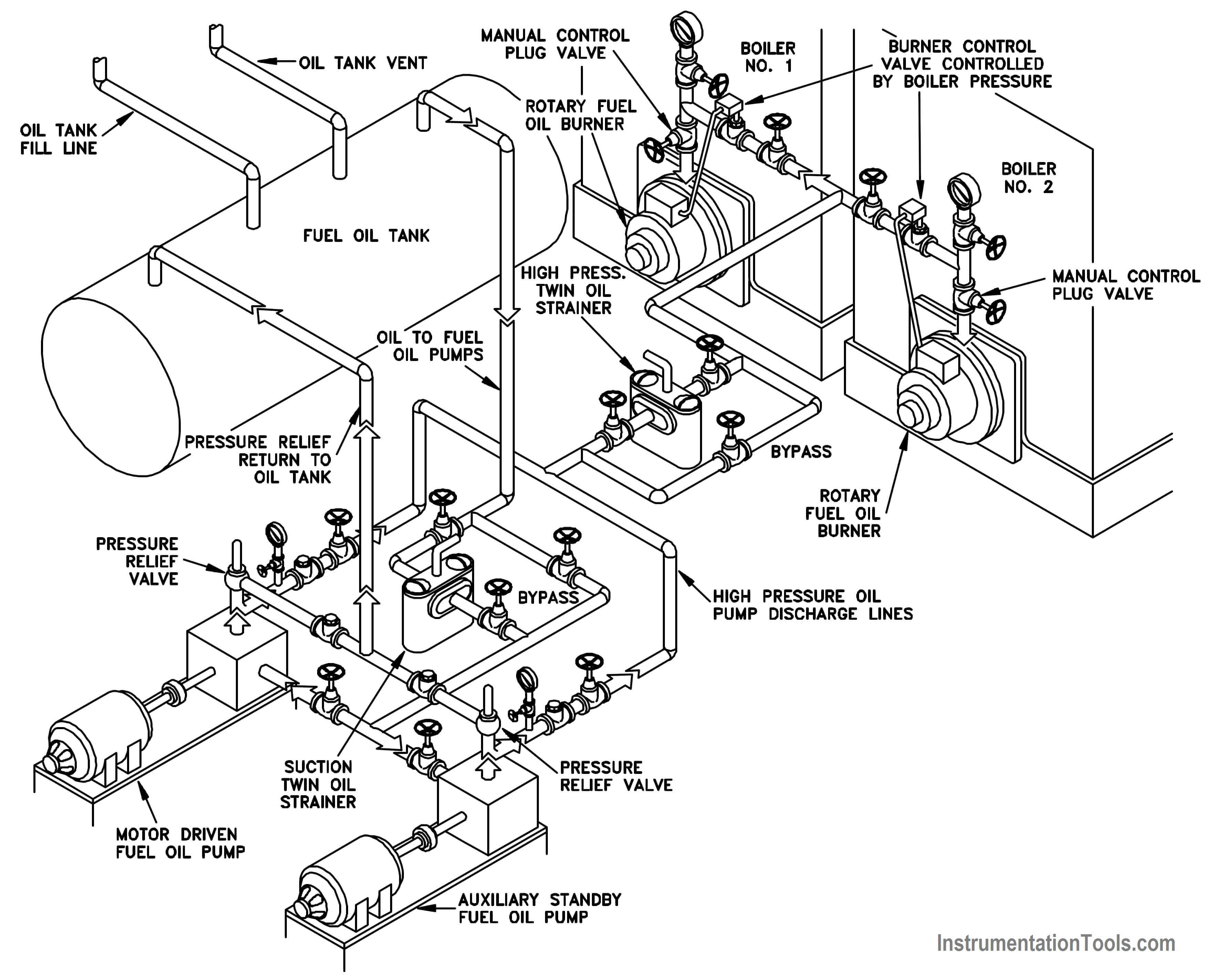
All system equipment is represented by simple standard symbols covered in later modules.
P id drawings pdf. 3 aarx 304l s s 1 f 3 aarx 304l s s. Single line p id drawings. P id is the acronym for piping and instrumentation diagram i e. Pfd symbols may change from company to company bs 5070 iso 10628 and isa s5 1 12.
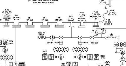
Figure 12 is an example of a single line p id. Rely on auto create diagram software to gain better piping and instrumentation diagrams. The single line format is most commonly used in p ids. 6 3 2 drawings sheet sizes diagrams shall be shown on a0 size 841 mm 1189 mm tracing paper.
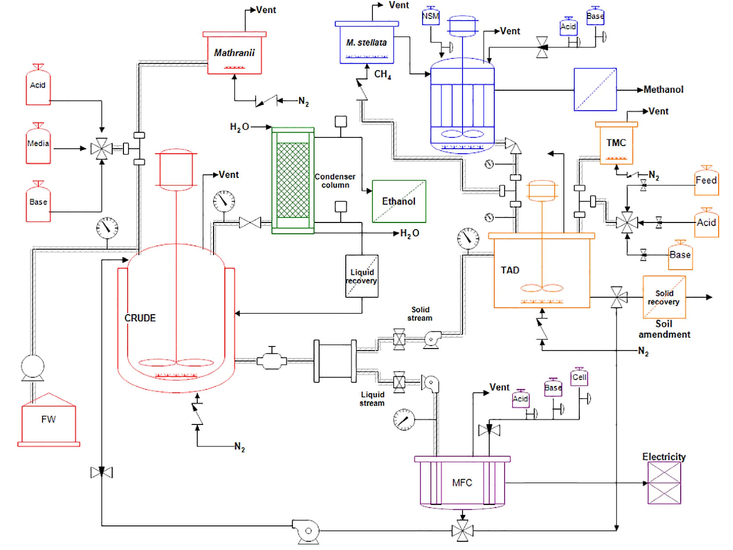
A very detailed diagram showing the processes happening within a plant the involved equipment and their interconnections. 6 3 3 drawing title block. The grid can consist of letters numbers or both that run horizontally and vertically around the drawing as illustrated on figure 2. Detailed graphical representation of a process including the hardware and software i e piping equipment and instrumentation necessary to design construct and operate the facility.
The single line format represents all piping regardless of size as single line. Piping and instrumentation diagram p id. A set of standardized p id symbols is used by process engineers to draft such diagrams. To help locate a specific point on a referenced print most drawings especially piping and instrument drawings p id and electrical schematic drawings have a grid system.
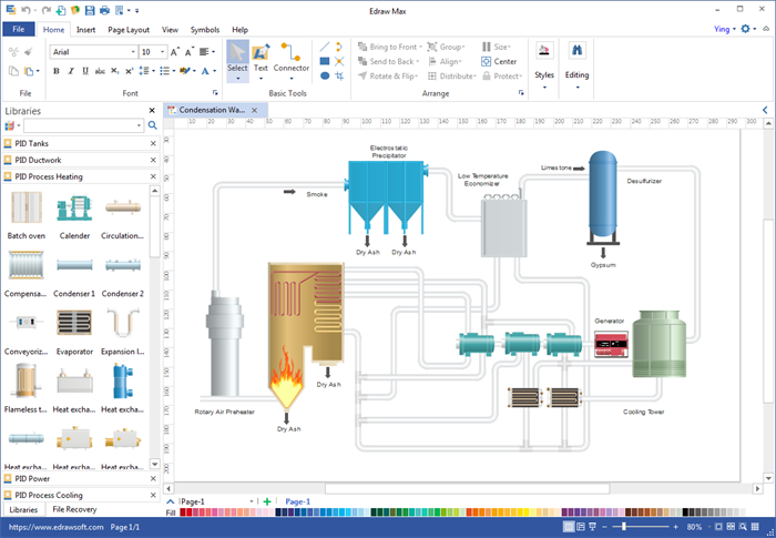
Spec breaks a line code changes every time any element in the code changes ie 3 aarx 304l s s 1 f 3 aarx 304l s s at the point where the fluid has cooled enough to eliminate the insulation. Piping and instrument diagram standard symbols detailed documentation provides a standard set of shapes symbols for documenting p id and pfd including standard shapes of instrument valves pump heating exchanges mixers crushers vessels compressors filters motors and connecting shapes. Common synonyms for p ids include engineering.


