Sample P Id Drawings Pdf
If you are trying to document piping processes this is your perfect start.
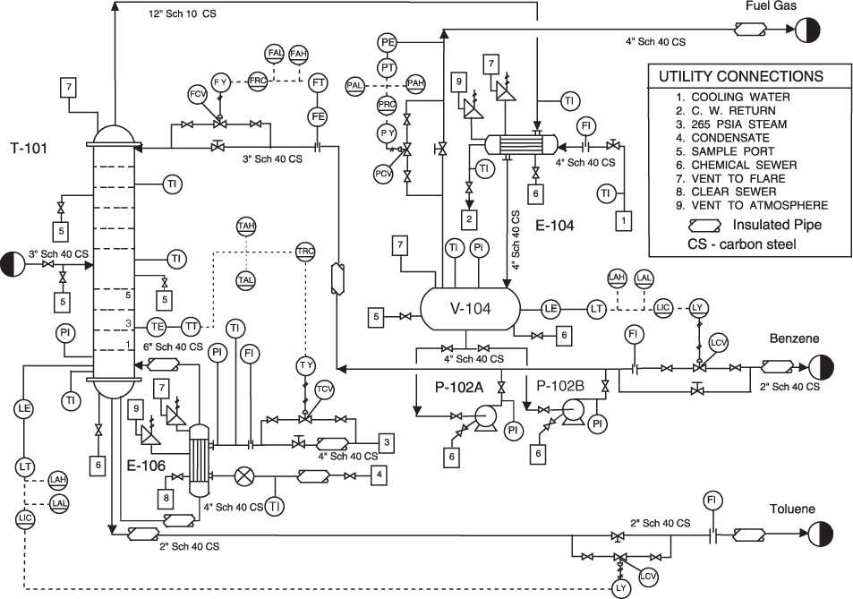
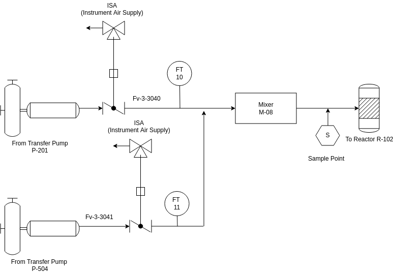
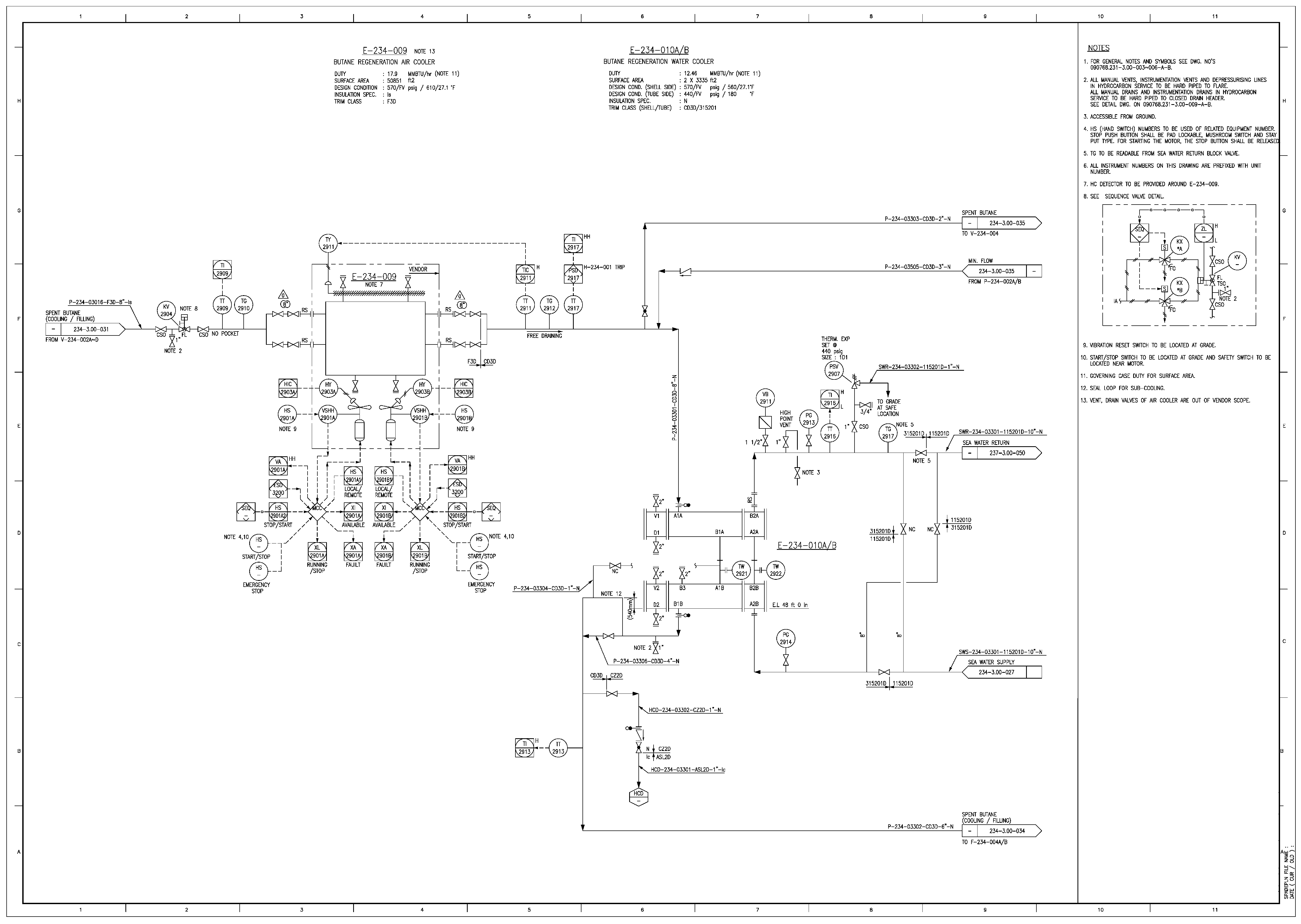
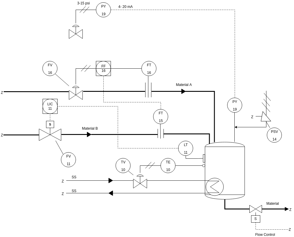
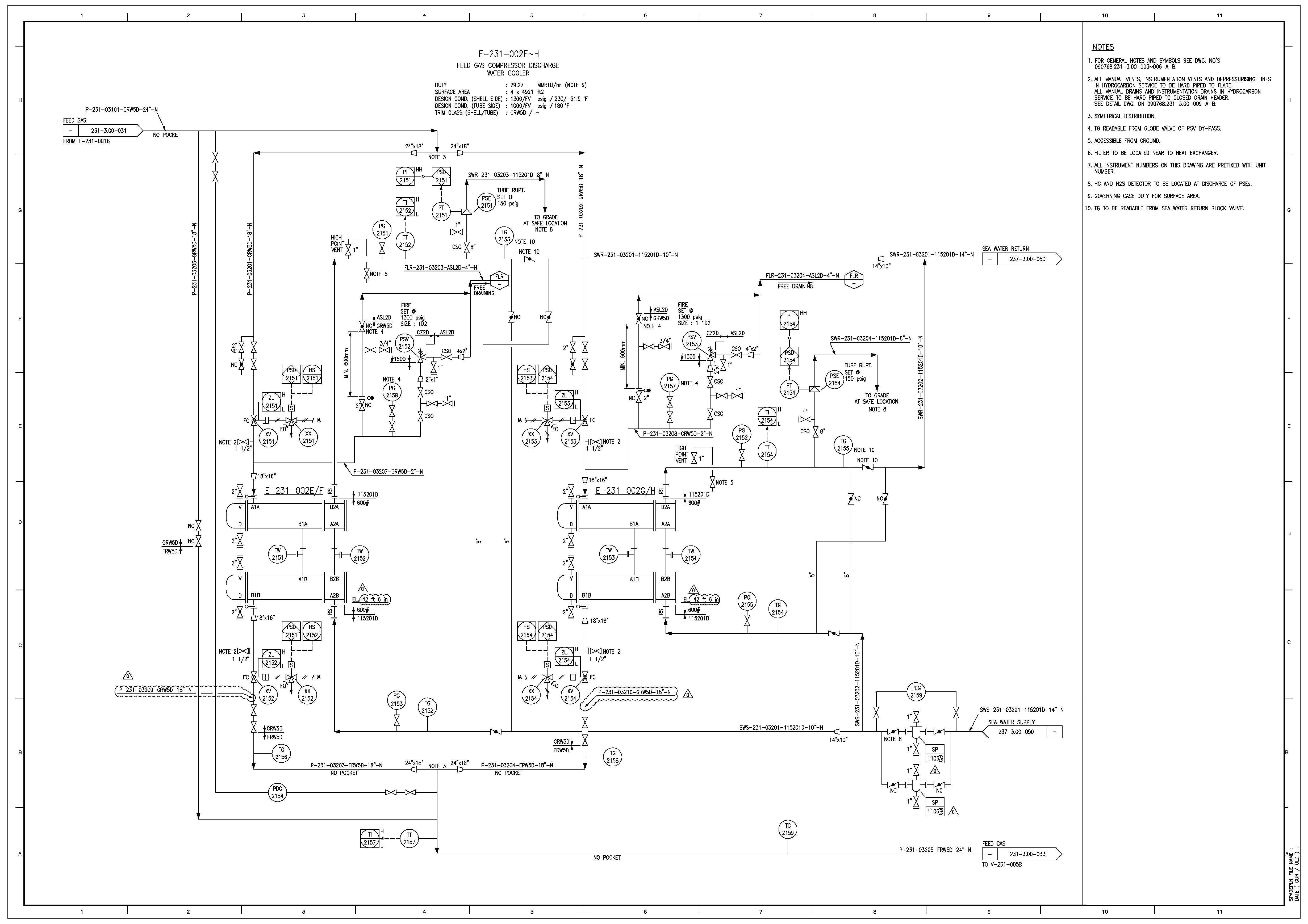
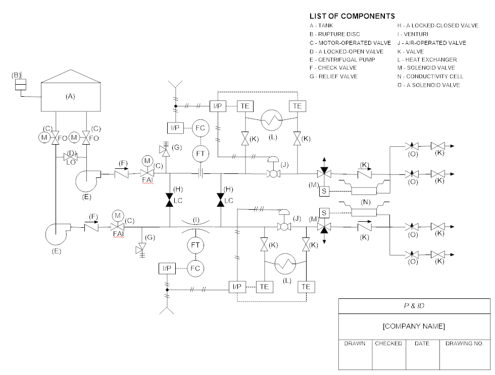
Sample p id drawings pdf. 6 3 2 drawings sheet sizes diagrams shall be shown on a0 size 841 mm 1189 mm tracing paper. To help locate a specific point on a referenced print most drawings especially piping and instrument drawings p id and electrical schematic drawings have a grid system. 2 in the project properties project settings dialog box click default to switch on all paths for pneumatic hydraulic and p id schematic libraries. A set of standardized p id symbols is used by process engineers to draft such diagrams.
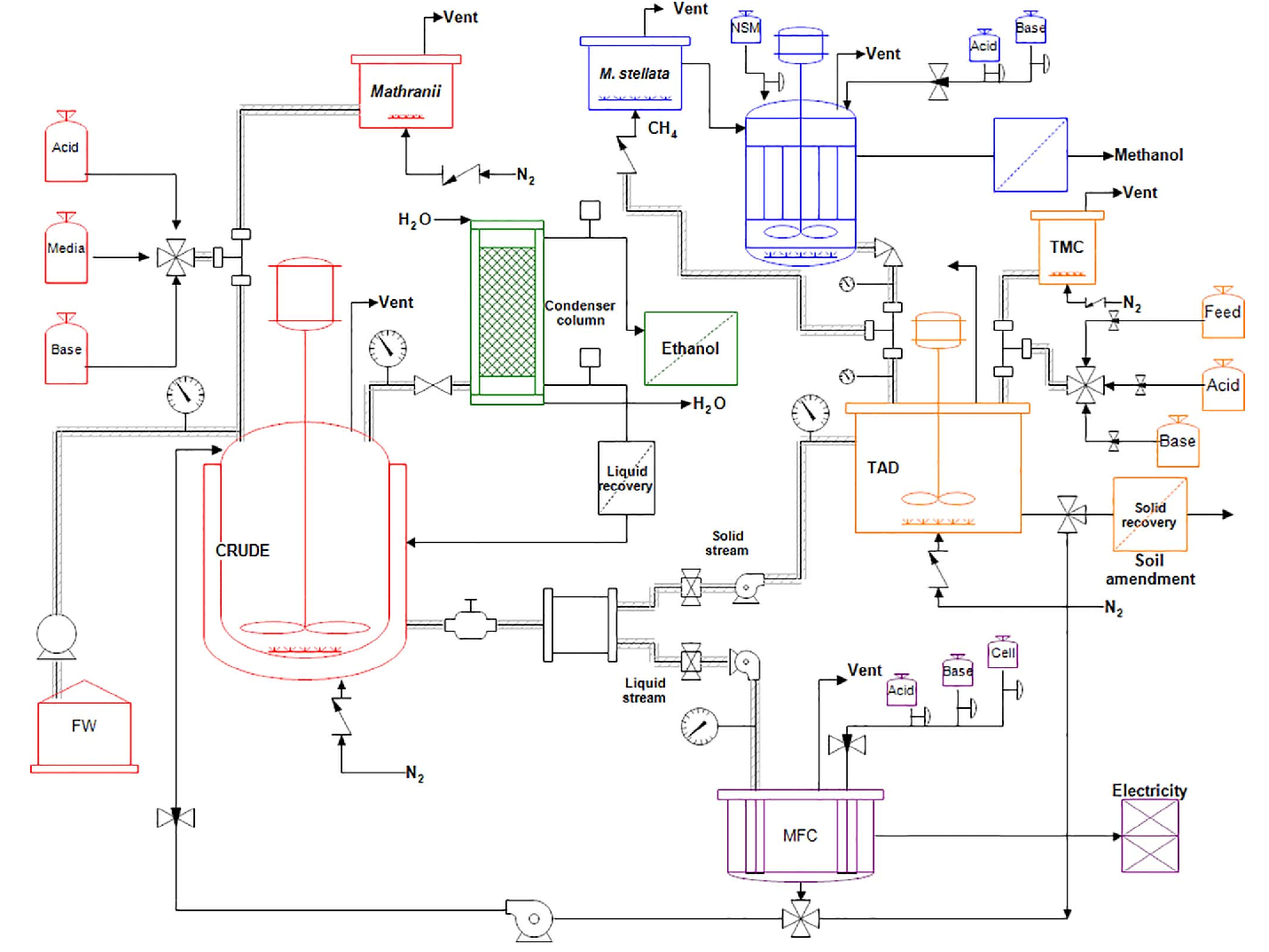
A very detailed diagram showing the processes happening within a plant the involved equipment and their interconnections. Create a new drawing 1 in the project manager right click the project name and select properties. Pfd symbols may change from company to company bs 5070 iso 10628 and isa s5 1 12. 6 3 3 drawing title block.
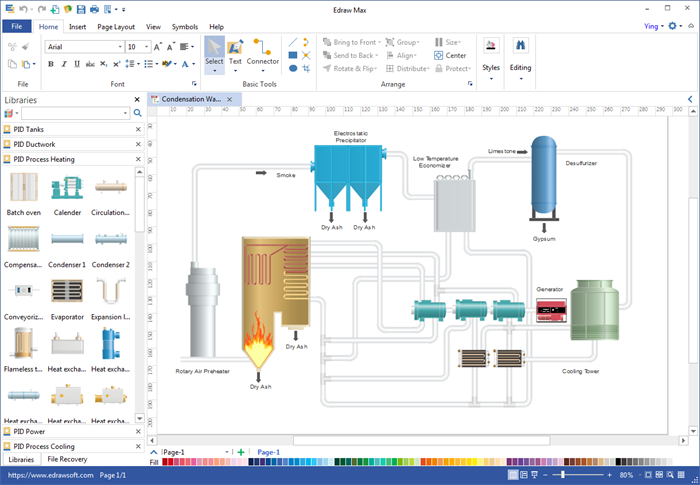
Can create a new drawing and modify any drawing properties. Process instrumentation diagram graphical description of the process and process equipmentgraphical description of the process and process equipment using standard symbols ansi isa s5 1 instrumentation symbols and identification the p id is used by field technicians engineers and operators to better understand the process and how the. The grid can consist of letters numbers or both that run horizontally and vertically around the drawing as illustrated on figure 2. Environmental p id example auxilary system p id example distribution p id example all equipment shapes you see in the examples are prepared in the edraw p id software.
A1 size 591 mm 841 mm may be used for simple p ids and ufds as per company s approval see article 6 3 3 2 for drawing dimensions and title block sizes. As it s a drag and drop based drawing tool you don t need to have drawing skills. 3 aarx 304l s s 1 f 3 aarx 304l s s. This practice applies to all diagrams that fit the definition of a p id in section 3.


