What Is A Block Diagram In Electronics
Block Diagram Tutorial Block Diagrams Electronics Circuit And Tutorials Hobby Science Projects

What Is A Block Diagram In Electronics Quora

Drafting For Electronics Block Diagrams

Electronic Circuits Block Diagram Download Scientific Diagram
What Is Block Diagram Everything You Need To Know
Hardware Block Diagram Cam S Electronics Projects

Ask block diagram amplitude shift keying theory in amplitude shift keying the phase and frequency of the carrier wave are maintained at a constant level and only its amplitude is varied in accordance with the digitalized modulating signal.
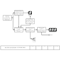
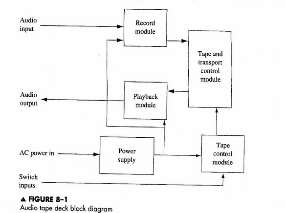
What is a block diagram in electronics. Its structure provides a high level overview of major system components key process participants and important working relationships. For example here s the block diagram of a power supply circuit. Block diagram of instrumentation system author. Block diagrams are typically used for higher level less detailed descriptions that are intended to.
Block diagrams are generally used when the visualization of information or control flows is important or when processes are involved. An entity relationship diagram erd one example of a block diagram represents an information system by showing the. They are heavily used in engineering in hardware design electronic design software design and process flow diagrams. Block diagrams are used to understand and design complete circuits by breaking them down into smaller sections or blocks.
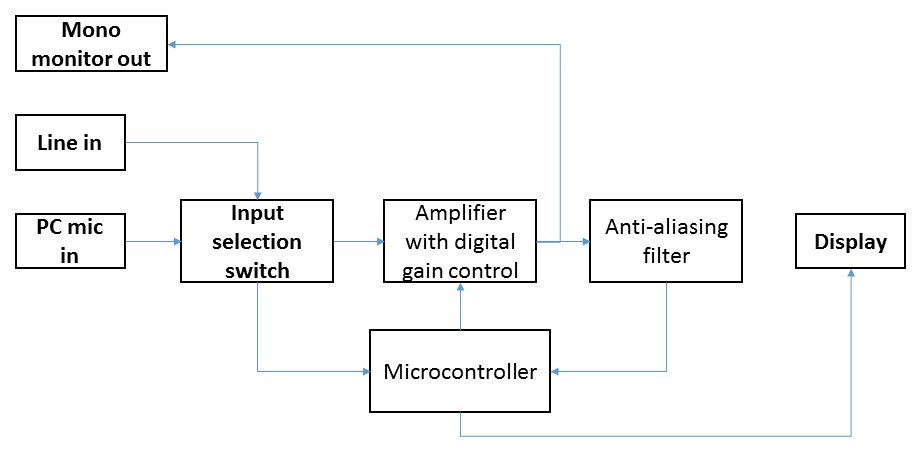
Block diagram what is a block diagram. Block diagram tutorial block diagrams electronics circuit and tutorials hobby science projects modulation enables low frequency audio signals to be radiated long distances. This is done by superimposing the low frequency audio signal on the high frequency carrier wave by the process of modulation. Each block performs a particular function and the block diagram shows how they are connected together.
Block diagram in electronics consists of a connection of smaller standard circuits which in turn consists of the special arrangement of components performing a circuit task. No attempt is made to show the components used within a block only the inputs and outputs are shown. A block diagram is a visual representation of a system that uses simple labeled blocks that represent single or multiple items entities or concepts connected by lines to show relationships between them. A block diagram is a diagram of a system in which the principal parts or functions are represented by blocks connected by lines that show the relationships of the blocks.
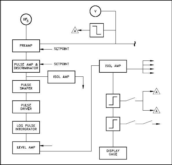
As we can see it consists of various units the operation of each is discussed below. The figure below shows the block diagram of the digital instrumentation system. Mechatronic systems in the trucking industry. A transducer is a device that changes the physical quantity to be measured into its equivalent electrical form.
Block diagrams are used in electronics to represent systems and their shifting e g. It is used to design new systems or to describe and improve existing ones.

Block Diagram Of The Signal Processing Electronics Download Scientific Diagram
Develop A Circuit Block Diagram Of The Circuit Sys Chegg Com

Block Flow And Single Line Diagrams
Electronic System

Explained Electronic Ballast Circuit Diagram And Working Etechnog
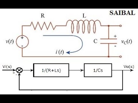
How To Draw The Block Diagram Of Any Electrical Circuit From Transfer Function Youtube

Functional Block Diagram Wikipedia

What Is Power Electronics And Its Block Diagram Quora
Circuit Diagram Wikipedia

Bluetooth Controlled Home Electronic Appliances Block Diagram Electronic Appliances Home Automation System Home Automation

Circuit Block Diagram Download Scientific Diagram
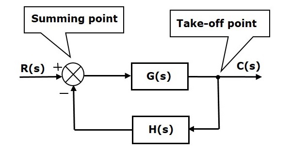
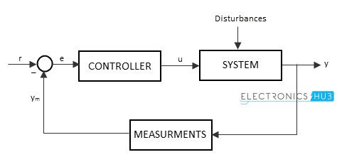
Control Systems Block Diagrams Tutorialspoint
Electronic Circuit Designing Functional Block Designing Part 3