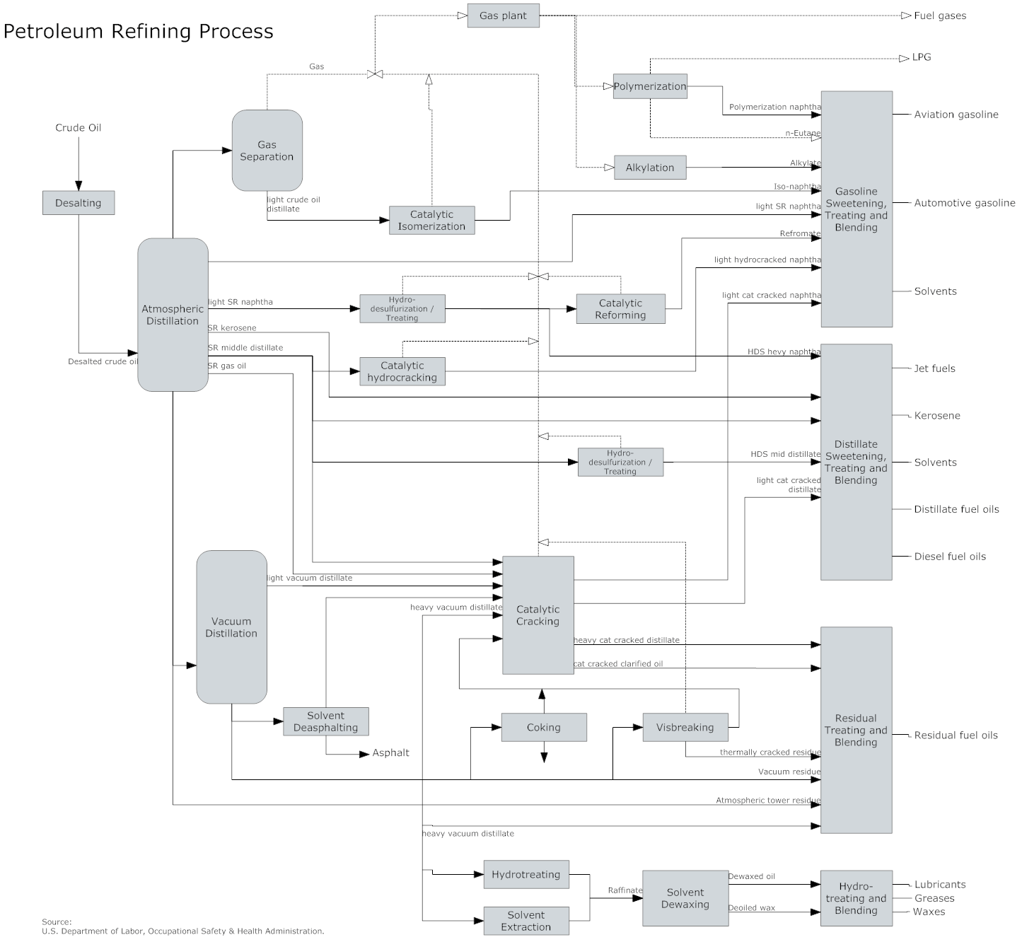
What Is A Block Flow Diagram
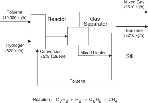
A bfd generally consists of the following.
What is a block flow diagram. They are heavily used in engineering in hardware design electronic design software design and process flow diagrams. Process flow streams may be mixtures of liquids gases and solids flowing in pipes or ducts or solids being carried on a conveyor belt. These are also called block flow diagrams and schematic flow diagrams. It is used to display the essential elements of the system through simple and clear interconnectedness.
The term functional in this context is different from its use in functional programming or in mathematics where pairing functional with flow would be ambiguous. Basic elements of block diagram. Block diagram what is a block diagram. Each block can depict a single piece of equipment or a stage in a process.
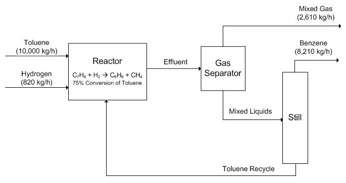
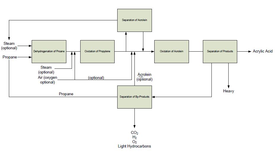
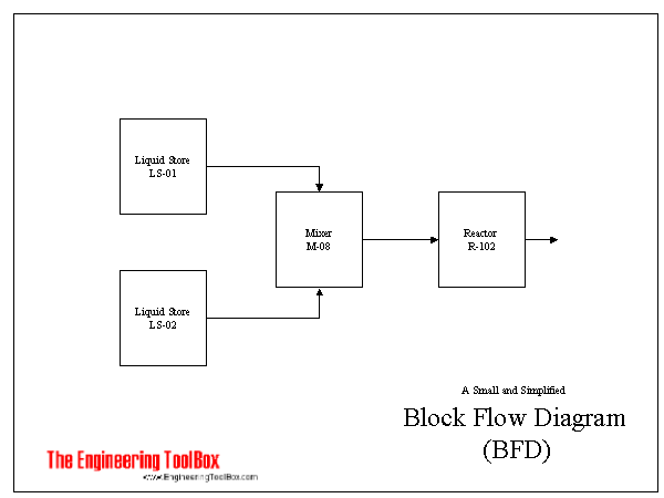
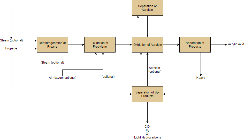
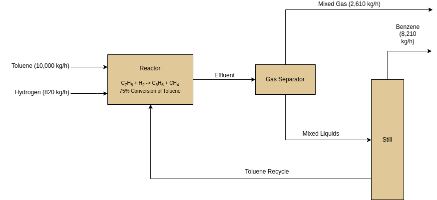
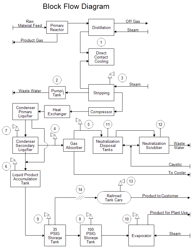
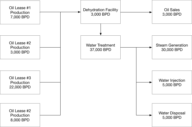
Rectangles in block flow diagrams represents unit operations. Blocks in a bfd can represent anything from a single piece of equipment to an entire plant. A block flow diagram bfd sometimes referred to as an iconic flow diagram provides an outline of a process on just one or two sheets. While studying one it is very crucial to keep in mind that a block diagram only represents flow paths of control signals.
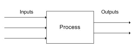
A block diagram is a diagram of a system in which the principal parts or functions are represented by blocks connected by lines that show the relationships of the blocks. Let us consider the block diagram of a closed loop control system as shown in the following figure to identify these elements. Here functional flow pertains to the sequencing of operations with flow arrows expressing. A rectangle is usually used to show a piece of equipment and labels illustrate function.
Symbols for the larger equipment items or for groups of equipment. Blocks are connected by straight lines representing process flow streams. A block flow diagram bfd is a drawing of a chemical processes used to simplify and understand the basic structure of a system. A bfd is the simplest form of the flow diagrams used in industry.
Block diagrams are typically used for higher level less detailed descriptions that are intended to. It is not to scale and will contain only very limited engineering and process information. Connectors and symbols work together to illustrate directions of flow objects that move and quantities. The process flow is usually shown from left to right and arrows show flow direction.
The third block diagram example is of a feedback control system. It is used to design new systems or to describe and improve existing ones. A block diagram is a specialized high level flowchart used in engineering. A flow diagram or flowchart is a specific type of activity diagram that communicates a sequence of actions or movements within a complex system.
The above block diagram consists of two blocks having transfer functions g s and h s. The basic elements of a block diagram are a block the summing point and the take off point.
