What Is Block Diagram In Control System
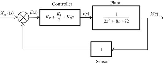
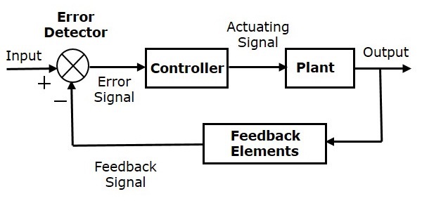
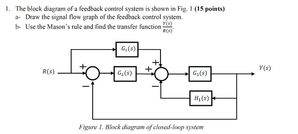
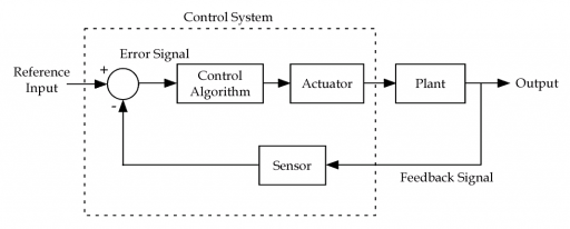
These are used to represent the control systems in pictorial form.
What is block diagram in control system. By equation 7 3 the output c due to input u is c g2 1 g1g2 u. Block diagrams consist of a single block or a combination of blocks. In other words practical representation of a control system is its block diagram. Note that this table is from schaum s outline.
7 let the 1 block be absorbed into the summing point. The block diagram representation is a combination of these two methods. Block diagrams derive their name from the rectangular elements found in this type of diagram. A block diagram is a graphical representation of a system it provides a functional view of a system.
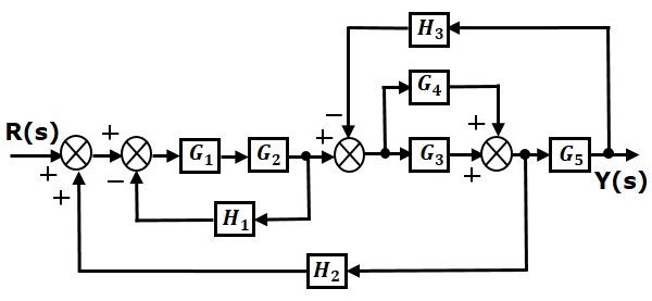
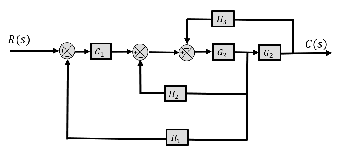
The total output is c c c 1 g2g2 a a igir 7 8 reduction of complicated block diagrams the block diagram of a practical feedback control system is often quite complicated. Block diagrams give us a better understanding of a system s functions and help create interconnections within it. It is easier and better to derive the transfer function of the control element connected to the system separately. A block diagram is a visual representation of a system that uses simple labeled blocks that represent single or multiple items entities or concepts connected by lines to show relationships between them.
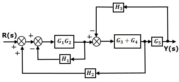
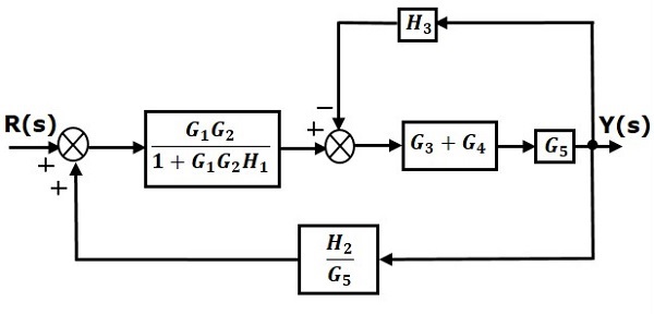
Block diagrams can be systematically simplified. The simplest form of a block diagram is the block and arrows diagram. Block diagram in control systems. Thus it is always better to draw the block diagram of the system in the easiest possible way thereby making the analysis simple.
The block diagram reduction process takes more time for complicated systems. Step 4c step 5. It is not always convenient to derive the entire transfer function of a complex control system in a single function. However these methods do not work for complicated systems.
An entity relationship diagram erd one example of a block diagram represents an information system by showing the. The block diagram is to represent a control system in diagram form. Feedback and controls systems by distefano et al. Some systems may have dedicated summation or multiplication devices that automatically add or multiply the transfer functions of multiple systems together simplifying block diagrams.
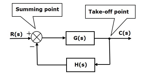
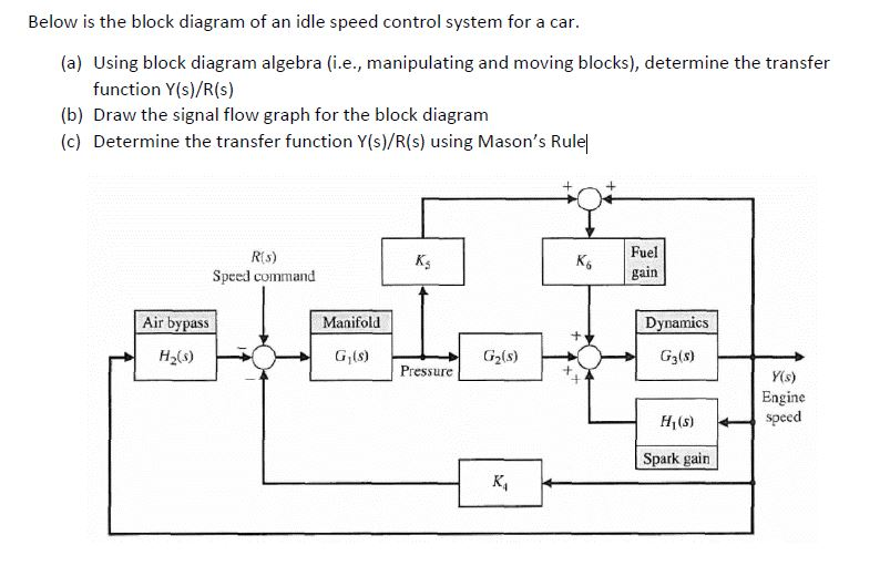
The basic elements of a block diagram are a block the summing point and the take off point. Because we have to draw the partially simplified block diagram after each step. So to overcome this drawback use signal flow graphs representation. A block diagram is a pictorial representation of the cause and effect relationship between the input and output of a physical system.
Basic elements of block diagram. But as we also know that the block diagram representation of a system involves summing points functional blocks and take off points connected through branches and flow of signal shown by the arrowheads.
