P Id Drawing Full Form
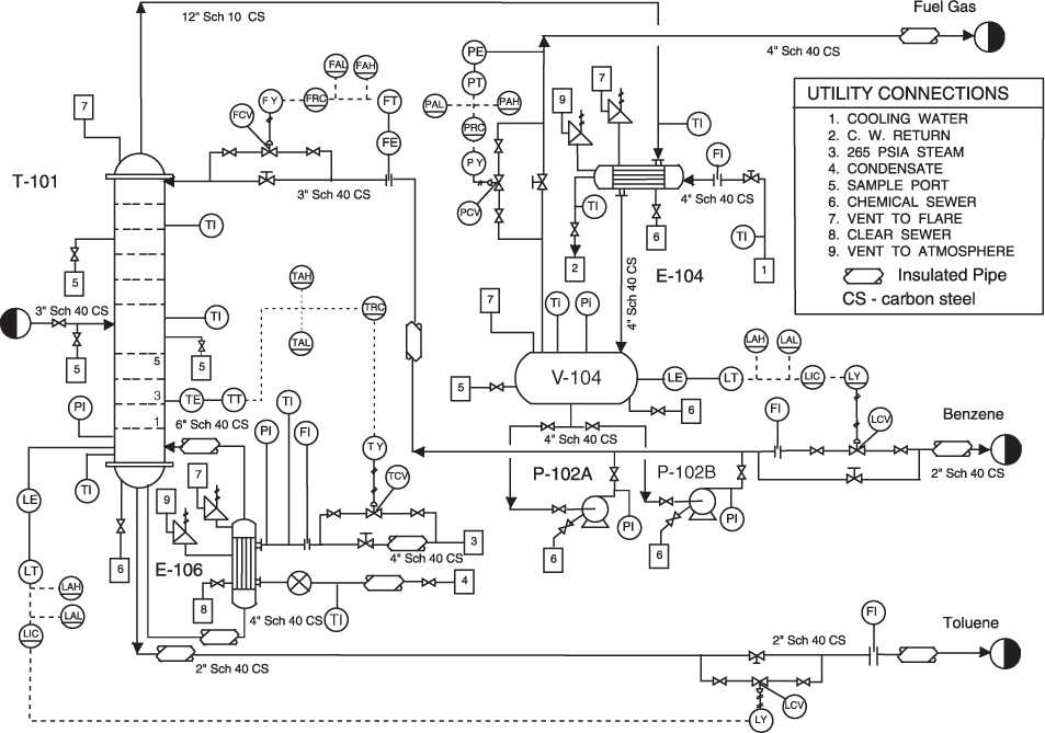
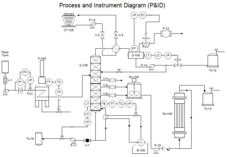
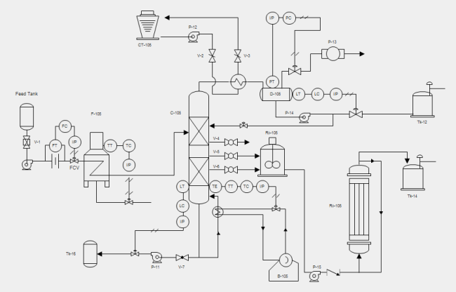
P id symbols are a graphical representation of physical equipment that installed on the field.
P id drawing full form. Pfd means process flow diagram and p id means piping and instrumentation diagram. A p id should include. Standard symbols are used for drawing p id. Please don t get scared.
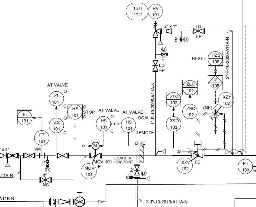
Whenever you start reading a piping drawing or document you can see many abbreviations on these drawings documents. There are few iso and british standards available that provide symbols and best practices to draw pfd and p id such as isa s5 1 bs 5070 and iso 10628. P id s shows all piping including physical sequences of branches reducers valves equipment instrumentation and control interlocks. In this article chemical tweak will explain you the basic p id diagrams which will help to understand process and instrumentation.
P id and pfd symbols. The instrumentation abbreviations table used in p id the table below contains some of the instrument abbreviations adapted from isa standard s5. P id diagram plays an important role in any industries to have a overview of process flow along with equipments and valves. One easy way to learn how to read p id drawings and become proficient in it is to look at a lot of piping and instrumentation diagrams.
P id diagram online drawing tool. Many abbreviations are common and are regularly used in the drawings but few of the abbreviation are new and unique for a particular drawing. Both simple and complex ones. All valves and their.
Superordinate to the p id is the process flow diagram pfd which indicates the more general flow of plant processes and the relationship between major equipment of a plant facility. Mechanical equipment with names and numbers. The main objective of bringing many possible combinations of these process instruments is to drive home the understanding of how they are formed such that once you see them being used in a process or instrumentation diagram or even conceptual or flow diagrams you will immediately be in a position to identify them and know what they are being used for. A piping and instrumentation diagram p id is a detailed diagram in the process industry which shows the piping and process equipment together with the instrumentation and control devices.
Pumps and turbine p id symbols. By so doing you will eventually become good at reading p ids. Each unit is represented by p id from p id we can understand wat are the instrument prresent in the plant and process related information like temperature pressure etc.


